Current Sensing Techniques in Electronic Circuits

Current measurement is one of the most common and important functions in modern electronic systems. Whether designing a battery-powered device, industrial motor controller, power supply, electric vehicle subsystem, or renewable energy application, engineers often need accurate information about how much current is flowing through a circuit. Likewise, component buyers and sourcing professionals must understand current sensing requirements to select suitable sensors, amplifiers, shunt resistors, and supporting components.

Current sensing serves several purposes. It can be used for system monitoring, overload protection, energy management, efficiency optimization, fault detection, closed-loop control, and regulatory compliance. The challenge is that no single sensing method is ideal for every application. Designers must balance accuracy, cost, isolation requirements, power loss, bandwidth, and environmental considerations when choosing a solution. We will explore the most common current sensing techniques used in electronic circuits and discuss the advantages, limitations, and typical applications of each approach.


Why Current Sensing Matters

Unlike voltage, current cannot be measured directly by simply probing two points in a circuit. Current measurement requires detecting the magnetic field or voltage drop associated with current flow and then converting that information into a usable signal.

In many systems, current measurements provide valuable insight into operating conditions. Motor controllers use current feedback to regulate torque and detect stalls. Battery management systems monitor charge and discharge currents to estimate the state of charge and protect cells. Power supplies rely on current sensing to implement overcurrent protection and maintain stable operation. Industrial equipment uses current measurements to identify faults before they become catastrophic failures. As electronic systems become increasingly intelligent and connected, accurate current sensing continues to play a growing role in system diagnostics and predictive maintenance.


Shunt Resistor Current Sensing

The most widely used current sensing technique is the shunt resistor method. This approach relies on Ohm’s Law, which states that the current through a resistor can be calculated given the voltage and resistance. A precision resistor with a very low resistance value is placed in series with the load. As current flows through the resistors, a small voltage drop appears across it. This voltage can then be measured.

For example, a 1 mΩ shunt resistor carrying 10 amps produces a voltage drop of 10 millivolts. A current-sense amplifier or differential amplifier can then amplify this signal for processing by a microcontroller, ADC, or control circuit.

Shunt resistor sensing offers several advantages. It is relatively inexpensive, very accurate, and capable of measuring both AC and DC currents. It also provides excellent linearity and can achieve very high bandwidth, making it useful in switching power supplies and motor control applications. However, shunt resistors introduce power loss because they are intentionally placed in the current path. At higher currents, even a small resistance can generate significant heat. Designers must carefully consider resistor power ratings, thermal performance, and temperature coefficients to maintain measurement accuracy. For many low- to medium-power applications, shunt-based sensing remains the preferred solution because of its simplicity and cost-effectiveness.


Low-Side vs. High-Side Current Sensing

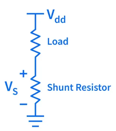
When using shunt resistors, designers must decide whether to place the resistor on the low side or high side of the load. Low-side current sensing positions the shunt between the load and ground. Because the measurement occurs near ground potential, the sensing circuitry is simpler and typically less expensive. Many operational amplifiers and current-sense amplifiers can easily process these small voltage signals. The primary disadvantage is that the load no longer sits directly at system ground. The voltage drop across the shunt creates a slight ground offset that may interfere with sensitive circuitry.

High-side current sensing places the shunt between the power source and the load. This configuration allows the load to remain directly connected to ground while enabling detection of certain fault conditions, such as short circuits to ground. The challenge is that the measurement circuitry must accurately detect a small differential voltage while operating at a much higher common-mode voltage. Specialized high-side current-sense amplifiers are often required. Many modern power electronics designs favor high-side sensing because of its improved system visibility and diagnostic capabilities.


Hall Effect Current Sensing

Hall effect sensors measure current by detecting the magnetic field generated by a current-carrying conductor. Instead of placing a resistor directly in the current path, the sensor monitors the surrounding magnetic field and converts it into a proportional electrical signal. One major advantage of Hall effect sensing is galvanic isolation. Since there is no direct electrical connection between the measured conductor and the sensing electronics, designers can safely monitor high voltages while protecting sensitive control circuitry.

Hall-effect sensors also exhibit minimal power loss because they do not require a series resistor that dissipates energy. This makes them attractive for high-current applications such as motor drives, battery systems, solar inverters, and industrial automation equipment. The trade-off is that Hall-effect sensors generally provide lower accuracy than precision shunt-based solutions. Temperature variation, magnetic interference, and offset drift can affect performance. While modern Hall effect devices have improved substantially, designers must still account for these factors during system development.


Current Transformers

Current transformers, often called CTs, are widely used for AC current measurement in industrial and power distribution systems. A current transformer operates using electromagnetic induction. The conductor carrying the measured current acts as the primary winding, while the transformer contains a secondary winding that produces a proportional current or voltage signal. Because transformers rely on changing magnetic fields, they only work with AC currents. They cannot measure pure DC current.

Current transformers offer several benefits, including excellent isolation, low insertion loss, and the ability to measure very large currents safely. They are commonly found in power monitoring equipment, energy meters, protective relays, and industrial control systems. For applications involving DC current measurement, designers must look to other technologies, such as the previously discussed shunt resistors or Hall-effect sensors.


Selecting the Right Current Sensing Method

Choosing the best current-sensing technique depends on the application's requirements.  For cost-sensitive designs that require high accuracy, shunt-resistor sensing is often the strongest option. For high-voltage systems where isolation is critical, Hall-effect sensors offer an attractive balance between performance and safety. Current transformers excel in AC power monitoring applications. There are even advanced, expensive magnetic sensing technologies if the application demands extremely precise requirements. Engineers should also evaluate factors such as measurement range, bandwidth, power dissipation, temperature stability, available board space, isolation requirements, and long-term reliability. In many cases, current-sensing solutions influence not only measurement performance but also overall system efficiency and safety.


Conclusion

Current sensing is a foundational function in modern electronic design. From battery-powered consumer products to industrial automation systems, accurate current measurement enables protection, control, diagnostics, and energy management. Shunt resistors, Hall-effect sensors, current transformers, and advanced magnetic sensing technologies each offer unique advantages and trade-offs. Understanding these differences allows engineers to select the most appropriate solution for their application while helping procurement teams source the right components to support long-term system performance.

As power electronics, electrification, and intelligent monitoring systems continue to expand across industries, effective current sensing will remain a critical design consideration for both engineers and electronic component buyers.

Did you find this article useful? Share it!

Join the circuit, keeping you connected to OnlineComponents.com and beyond!