English
 中文 / 汉语
 Italiano
 Português
 Deutsch
 Français
 Русский
 日本語
 Türkçe
 한국어
 Español
 Nederlands

Shielding Techniques to Minimize Electromagnetic Interference
Few things are more frustrating than a design that works fine on the bench, then turns flaky in the field or fails EMC testing right when you thought you were done. Electromagnetic interference (EMI) is often the culprit. Stray electromagnetic energy can corrupt signals, add noise, drag down performance, and turn regulatory compliance into a much bigger headache than it needs to be. And it isn’t getting any easier. Products keep getting smaller and faster, and it’s now common to find a switching regulator, a fast processor, a wireless radio, and maybe a motor driver all sharing the same product, sometimes only a few centimeters apart.
That’s why good electromagnetic compatibility (EMC) takes more than bolting a metal box around the finished design. Effective shielding starts with understanding how interference actually moves through your system. Once you know that, you can pick the techniques that cut those paths off.
What Is EMI Shielding?
At its core, EMI shielding places conductive or magnetic material between a noise source and the circuit you want to protect, so less electromagnetic energy gets through. Depending on the problem, you might shield a single component, one region of a circuit board, a cable, a connector, or the entire enclosure.
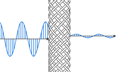
Shields do their job by reflecting and absorbing electromagnetic energy. Good conductors like copper and aluminum work well against electric fields and higher-frequency interference. Low-frequency magnetic fields are a different beast, and that’s where high-permeability materials earn their keep.
How well any of this works depends heavily on frequency, material, geometry, and how carefully it’s implemented. A shield that handles one noise source beautifully might barely touch another. That’s a big reason to treat EMI as a system-level design question rather than just a materials problem.
Start with the Source, the Path, and the Victim
Before you reach for a shielding solution, it helps to break the problem into three pieces.
The source is whatever is generating the unwanted energy. The usual suspects include switching power supplies, oscillators, digital clocks, processors, motors, and high-current switching circuits.
The coupling path is how that energy gets from the source to somewhere it shouldn’t be. It might be conducted along power or signal lines, capacitively coupled through electric fields, inductively coupled through magnetic fields, or radiated through space. The victim is the circuit or device that ends up misbehaving.
The nice thing about this framing is that you can go after any of the three. You can quiet the source, break the coupling path, or make the victim less sensitive. Often the best answer is a little of each.
Use Enclosures as EMI Shields
A conductive enclosure is probably the first thing most people picture when they hear “EMI shielding.” Done right, a metal enclosure puts a barrier between your electronics and the outside world, keeping your product’s noise in and everyone else’s noise out.
Aluminum, steel, and copper are all common choices. The best fit comes down to the frequencies you’re dealing with and how much shielding effectiveness you need, along with practical concerns like weight, mechanical strength, corrosion resistance, and cost.
Here’s the catch, though - putting electronics in a metal box doesn’t automatically make them shielded.
Every opening is a potential leak. Seams, vent holes, displays, switches, cable entries, and panels that don’t sit quite flush can all let energy through. At high enough frequencies, even a fairly small gap can become an effective path for electromagnetic energy. So keeping electrical continuity across seams really matters. Conductive gaskets, fingerstock, conductive coatings, and good mechanical fastening all help an enclosure hold onto its shielding performance while still leaving room for access, airflow, and assembly.
Shield Sensitive Areas at the PCB Level
You don’t always need to shield the whole product. A lot of the time, the trouble is concentrated around one component or one section of the board.
PCB-level shielding lets you isolate those spots without the size and weight of a fully shielded enclosure. Metal shield cans are commonly used around RF circuits, oscillators, processors, switching circuitry, and anything else that’s especially noisy or especially sensitive.
Layout matters just as much as the can. Solid ground planes, thoughtful component placement, short return paths, and some breathing room between noisy and sensitive circuits can cut down coupling before you ever need extra shielding.
That point is worth emphasizing, because shielding should back up good layout, not cover for a bad one. Dropping a shield over a problem circuit may bring emissions down, but taming the noise right where it starts will almost always give you a more dependable design.
Pay Attention to Cables and Connectors
Cables cause more than their share of EMI headaches, mostly because they’re long. All that length makes a cable a pretty good antenna. It can pick up interference from outside, or carry noise from inside your product out into the world and radiate it from there.
Shielded cable wraps the conductors in a conductive layer, usually foil, braided metal, or both. That conductive layer helps prevent electromagnetic fields from coupling to or from the conductors, and when it’s terminated properly, it can reduce interference dramatically. “Terminated properly” is doing a lot of work in that sentence. Even an excellent cable shield can lose much of its value if it passes through an unshielded connector or isn’t well bonded to the chassis. At higher frequencies, a long connection between the cable shield and ground can add enough inductance to undercut the whole thing.
That’s why it pays to treat cables, connectors, enclosure interfaces, and grounding as one EMI strategy instead of four separate decisions.
Combine Shielding with Filtering
Shielding is especially useful for controlling field coupling, but plenty of EMI problems also have a conducted side. Noise can ride along power lines, signal cables, and other conductors, walking right past an otherwise excellent enclosure.
That’s where EMI filters come in. Their job is to keep conducted noise from getting into or out of your system. Depending on the application, that might mean capacitors, inductors, ferrite beads, common-mode chokes, or an integrated EMI filter.
Shielding and filtering tend to work best as a team. The enclosure handles radiated coupling, and the filters deal with anything traveling along wires that cross the shield boundary.
Where you put the filter matters, too. If a cable runs well inside a shielded enclosure before it gets filtered, the noise it’s carrying has plenty of chances to couple into nearby circuitry first. In many designs, a filter does the most good right where the conductor enters or leaves the shielded area.
Don’t Overlook Grounding and Bonding
Grounding and shielding go hand in hand, but tying together everything labeled “ground” won’t magically fix an EMI problem. Where shield currents need to flow, they need an appropriately low-impedance path. At high frequencies, the shape and inductance of that path start to matter a lot. A long wire that reads as a perfect connection on your multimeter can present a surprising amount of impedance to high-frequency noise.
That’s why bonding deserves real attention. The connections between conductive surfaces, enclosure sections, cable shields, and PCB ground structures are all part of your EMI design.
There’s no one-size-fits-all grounding scheme, since the right approach depends on frequency and application. What you’re really after is control over where return currents flow, so unwanted energy can’t sneak into sensitive circuitry.
Design for EMI Before You Test
Shielding works best when EMC is part of the conversation from day one. If you wait until the product fails EMC testing, your options shrink fast. Once tooling is done and production is around the corner, changes to the PCB layout, connectors, cable routing, or enclosure get expensive.
Thinking about it early gives you a lot more room to work. You can keep noise sources away from sensitive circuits, build shielding provisions into the mechanical design, consider filtered connectors, and choose the right components while changes are still easy to make.
Testing is still essential, since electromagnetic behavior is notoriously hard to predict perfectly. Pre-compliance testing helps you catch problems sooner and gives you a chance to try out shielding and filtering fixes before you’re sitting in a formal EMC lab.
Putting It All Together
No single shielding technique will solve every EMI problem. Good electromagnetic compatibility comes from controlling how unwanted energy is generated, how it travels, and which circuits it can reach. Enclosures, PCB shields, shielded cables, EMI filters, grounding, and careful component placement each tackle a different piece of that puzzle. In practice, the best solution is usually a mix, chosen to fit the frequencies, noise sources, and physical constraints of your particular design.
For engineers, thinking about EMI early means fewer expensive fixes late in development. For buyers, understanding the full shielding strategy helps make sure the enclosures, connectors, filters, ferrites, and shielding materials you source meet the electrical requirements of the application, not just the mechanical ones.
OnlineComponents.com carries electronic components and interconnect products from a wide range of manufacturers, so engineering and procurement teams have plenty of options when sourcing parts for EMC-conscious designs. Picking the right components is only one part of electromagnetic compatibility, but getting those decisions right early makes for a product that’s easier to test, manufacture, and deploy with confidence.