English
 中文 / 汉语
 Italiano
 Português
 Deutsch
 Français
 Русский
 日本語
日本語
 Türkçe
 한국어
한국어
 Español
 Nederlands

Common Failure Modes of Passive Components and How to Avoid Them
Passive components are easy to underestimate and undervalue. Resistors, capacitors, inductors, ferrites, thermistors, varistors, and transformers rarely receive the same attention as microcontrollers, sensors, power semiconductors, or RF modules. Yet many electronic product failures trace back to a passive component that was incorrectly specified, poorly applied, mechanically stressed, thermally overloaded, or sourced without enough attention to quality and lifecycle risk. For electrical engineers and electronic parts buyers, understanding passive component failure modes affects product safety, warranty costs, field performance, and purchasing strategy. Many of these failures are preventable through proper derating, environmental awareness, approved sourcing, and careful substitution practices.
Resistor Failure Modes: Drift, Opens, and Overheating
Resistors can fail in several ways. One common failure mode is resistance drift, in which the actual resistance value changes over time due to excessive power dissipation, high operating temperature, humidity exposure, or stress. In precision circuits, even small changes in resistance can affect gain, bias points, sensing accuracy, or timing behavior. Open-circuit failure is another common issue, especially when a resistor is subjected to overload, surge energy, poor solder joints, or mechanical cracking. Current-sense resistors, startup resistors, pullups, pulldowns, and feedback resistors can all cause system-level faults if they fail open.
To reduce resistor failures, engineers should avoid operating resistors near their rated power limits. A resistor rated for a quarter watt may not perform reliably at that level in a compact enclosure with poor airflow. The resistor may need to be rated for a high power rating in those situations. Voltage rating should also be checked, especially in high-value resistors used in power supplies, line-connected equipment, and sensing circuits. Buyers should consider resistor technology, tolerance, temperature coefficient, surge rating, moisture resistance, and manufacturer quality rather than selecting only based on resistance value, package size, and price.
Capacitor Failure Modes: Dry-Out, Cracking, Leakage, and Breakdown
Capacitors are among the most failure-prone passive components because their behavior depends heavily on dielectric material, temperature, voltage, ripple current, frequency, and construction. Electrolytic capacitors are especially vulnerable to aging and dry-out. Over time, the electrolyte can evaporate or degrade, increasing equivalent series resistance and reducing capacitance. This can lead to power supply instability, excessive ripple, startup failures, or heat buildup. High operating temperature accelerates this process, so lifetime ratings must be evaluated against actual application conditions rather than assumed from the datasheet.
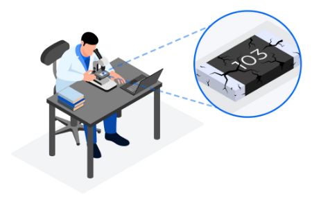
Ceramic capacitors have different risks. Multilayer ceramic capacitors, especially larger case sizes, can crack because of board flex, depanelization stress, pick-and-place force, thermal shock, or poor placement near connectors and mounting holes. A cracked MLCC may fail open, intermittently fail, or short. In power rails, a shorted ceramic capacitor can cause major board-level failures. Ceramic capacitors can also lose significant capacitance under DC bias, especially Class II dielectrics. This may become a functional failure if the circuit no longer has the required capacitance during operation.
To avoid capacitor failures, engineers should derate voltage appropriately, evaluate ripple current and ESR, check capacitance under DC bias, and select lifetime ratings based on actual temperature. Buyers should avoid unapproved substitutions, especially when dielectric type, ESR, ripple rating, safety certification, or component size affects performance.
Inductor and Transformer Failure Modes: Saturation and Heat
Inductors and transformers are often specified by inductance value first, but current rating, saturation current, DC resistance, core material, shielding, temperature rise, insulation rating, and frequency behavior are all critical. One common inductor failure mode is saturation. When an inductor exceeds its saturation current, its inductance can drop sharply. In switching regulators, this can increase ripple current, stress other components, generate excess heat, and create instability. Saturation may not immediately destroy the inductor but it can cause system-level failure or shorten the life of surrounding parts.
Thermal failure is another major concern. Inductors and transformers dissipate heat through copper losses, core losses, and frequency-dependent effects. If the part is undersized or placed in a hot area of the board, insulation can degrade, solder joints can fatigue, and winding resistance can increase.
To avoid these failures, engineers should check inductance at operating current, not just at zero current. Saturation current and RMS current should both be evaluated. For transformers, safety approvals, insulation class, hipot requirements, and agency compliance should be treated as core requirements.
Protection Components When Stressed
Protection and suppression components often fail because they are exposed to abnormal events by design. Ferrite beads, MOVs, NTC thermistors, PTC resettable fuses, and similar components are frequently placed at the boundary between the product and the outside world. That means they may see surges, inrush current, conducted noise, and repeated thermal cycling.
Ferrite beads can overheat if they are used in circuits with too much DC current or excessive AC ripple. MOVs can degrade after repeated surge events, causing their characteristics to shift and leakage to increase. NTC thermistors used for inrush limiting can fail if they do not have enough time to cool between power cycles or if the steady-state current exceeds their rating. For these components, the key is to design for real stress conditions. Surge energy, pulse duration, current waveform, ambient temperature, reset behavior, and safety requirements must be reviewed. Buyers should avoid swapping protection components based only on package size or nominal rating because these parts often protect the rest of the system.
Mechanical, Environmental, and Assembly-Related Failures
Not all passive component failures begin with the electrical design. Many are caused by the mechanical and environmental realities of manufacturing and field use. Board flex can crack ceramic capacitors and resistors. Poor solder profiles can create thermal shock, weak joints, tombstoning, or latent defects. Excessive rework can damage terminations. Vibration can stress larger components, especially tall electrolytic capacitors, transformers, and power inductors. Humidity, contamination, corrosive atmospheres, and inadequate cleaning can create leakage paths or corrosion.
Additionally, placement matters during the design phase. Components near connectors, board edges, mounting screws, heat sources, or high-vibration areas often experience greater stress. A passive component that is electrically correct may still be unreliable if it is mechanically exposed.
Procurement Practices That Reduce Passive Component Risk
For electronic parts buyers, passive component reliability is closely tied to sourcing discipline. Passive components are often treated as easy substitutes because they appear simple on the bill of materials. That assumption can create risk.
However, a capacitor substitution may change ESR, dielectric behavior, ripple current, lifetime, or DC bias performance. A resistor substitution may affect surge tolerance, temperature coefficient, voltage rating, or long-term stability. An inductor substitution may match the nominal inductance but differ significantly in saturation current, DCR, shielding, or thermal behavior.
A strong procurement process should include approved manufacturer lists, lifecycle review, authorized sourcing, and engineering approval for alternates. An IP&E distributor can help reduce risk by supporting cross-reference searches, identifying manufacturer-approved alternatives, checking lifecycle status, and helping buyers source from reliable supply channels.
Design Margin is The Best Reliability Tool
Most passive component failures come from some combination of electrical overstress, thermal stress, mechanical damage, environmental exposure, poor substitution, or inadequate derating. The best prevention strategy is to build margin into the design and protect that margin through proper purchasing and manufacturing. For engineers, that means reading beyond the first page of the datasheet. Check voltage, current, temperature, ripple, surge, tolerance, aging characteristics, dielectric behavior, saturation, and package limitations. For buyers, it means recognizing that two parts with the same nominal value are not automatically equivalent.
Passive components may not be the most visible parts of an electronic system, but they often determine whether a product performs reliably over time. Choosing them carefully, sourcing them responsibly, and applying them with an adequate margin is one of the simplest ways to prevent avoidable failures in the field.